
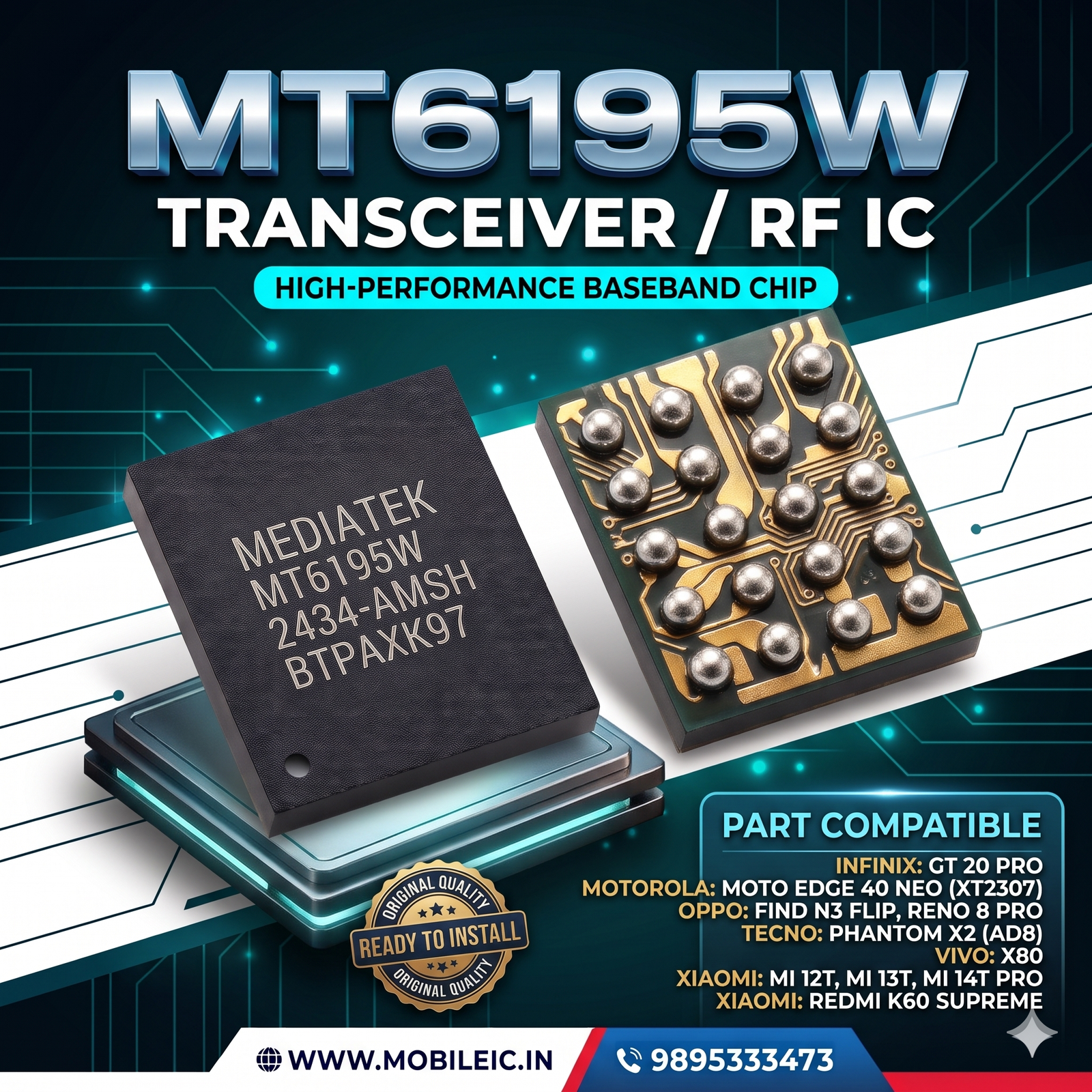
MT6195W mediatek ic
The MediaTek MT6195W is a radio frequency (RF) transceiver integrated circuit designed for mid-to-high-tier 4G LTE and 5G mobile handsets. Serving as the analog radio front-end interface directly coupled to the baseband processor/modem, this IC manages cellular signal conversion, modulation, demodulation, amplification filtering, and frequency synthesis across multiple cellular bands.
For professional motherboard micro-soldering technicians and mobile repair labs, this component is the primary hardware replacement for resolving persistent cellular connectivity, baseband communication, and radio frequency failures.
₹200.00

MT6195W mediatek ic
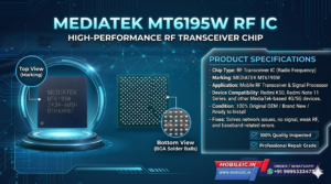
MediaTek MT6195W RF Transceiver IC (Brand New / OEM Grade)
The MediaTek MT6195W is a radio frequency (RF) transceiver integrated circuit designed for mid-to-high-tier 4G LTE and 5G mobile handsets. Serving as the analog radio front-end interface directly coupled to the baseband processor/modem, this IC manages cellular signal conversion, modulation, demodulation, amplification filtering, and frequency synthesis across multiple cellular bands.
For professional motherboard micro-soldering technicians and mobile repair labs, this component is the primary hardware replacement for resolving persistent cellular connectivity, baseband communication, and radio frequency failures.
Technical Specifications & Hardware Details
-
Part Number: MT6195W
-
Brand / Manufacturer: MediaTek
-
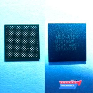
Standard Top-Side Laser Marking: MEDIATEK MT6195W 2434-AMSH BTPAXK97
-
Component Type: Radio Frequency (RF) Transceiver / Baseband Interface IC
-
Package Architecture: High-density Micro Ball Grid Array (BGA)
-
Ball Configuration: High-precision solder ball array for uniform thermal distribution and high-frequency grounding
-
Condition: 100% Brand New, Unused, Factory Fresh Stock
-
Solder Ball State: Pre-balled with lead-free alloy spheres ready for direct placement and reflow
-
Quality Grading: OEM Repair Grade, individually inspected under optical microscopy for pad continuity, ball coplanarity, and chip substrate integrity
Verified Compatible Models (Borneo Schematics Verified)
This transceiver is utilized across multiple modern MediaTek-powered smartphones:
Brand |
Compatible Model / Variant |
Infinix |
GT 20 Pro |
Motorola |
Moto Edge 40 Neo (Model: XT2307) |
OPPO |
Find N3 Flip, Reno 8 Pro |
Tecno |
Phantom X2 (Model: AD8) |
Vivo |
X80 |
Xiaomi / Redmi |
Mi 12T, Mi 13T, Mi 14T Pro, Redmi K60 Supreme |
Common Faults & Motherboard Diagnostic Symptoms
When the MT6195W develops internal solder fatigue, silicon degradation from overheating, or internal die damage after an impact or liquid ingress, it manifests in specific motherboard-level symptoms:
-
“No Service” or Persistent “Searching…” Loop:
-
The SIM card is detected, but the modem cannot register on cellular carrier networks or complete the network handshake.
-
-
Emergency Calls Only / No Radio Transmission:
-
The receiver or transmitter stages fail to lock onto local cellular towers, preventing outgoing and incoming cellular traffic.
-
-
Weak Cellular Signal / Dropped Bands:
-
Device connects to basic 2G or 3G but constantly drops or fails to lock onto 4G LTE or 5G frequency bands.
-
-
Unknown Baseband / IMEI Not Found:
-
The baseband firmware fails to initialize communication with the RF transceiver, resulting in blank baseband versions in device settings or modem crash logs.
-
-
Secondary RF Rail Short Circuits:
-
Short-to-ground conditions detected on the RF low-dropout (LDO) power lines (such as VREG_RF, VDD_RF, or local PLL supply lines), leading to excessive standby battery drain or board-level shutoffs.
-
Pre-Installation Diagnostic Checklist
Before replacing the MT6195W IC, ensure standard line testing is performed:
-
Check diode mode values on surrounding decoupling capacitors against standard schematic reference values (e.g., Borneo Schematics / ZXW) to confirm whether lines are shorted, open, or normal.
-
Verify incoming supply voltages from the sub-PMIC / PMIC during the boot cycle.
-
Inspect RF coaxial cables, antenna switches, and Power Amplifier (PA) modules to rule out exterior path breaks.
Professional Micro-Soldering & Installation Guide
⚠️ WARNING: Thermal Sensitivity BGA transceiver ICs are highly sensitive to uneven heat distribution and excessive soaking temperatures. Always protect adjacent shielded components (such as CPU, UFS/eMMC memory, and power management units) using heat-resistant kapton tape, ceramic fiber pads, or thick copper shims.
-
Board Preparation & Masking:
-
Secure the motherboard in a dedicated PCB fixture. Apply thermal shielding over nearby processors, memory chips, and underfilled modules.
-
-
Removal of Defective IC:
-
Apply high-temperature, no-clean BGA flux around the chip perimeter.
-
Using a hot air rework station with an appropriate circular nozzle, heat the IC evenly at approximately 330°C–350°C (adjust depending on station airflow and nozzle size) until the solder liquefies.
-
Carefully lift the chip vertically with precision tweezers without applying lateral force to avoid tearing motherboard copper traces.
-
-
Pad Dressing & Cleaning:
-
Apply flux and use a fine copper desoldering wick alongside a chisel soldering tip to clear remaining factory solder.
-
Ensure all motherboard pads are completely flat, shiny, and level. Clean thoroughly with high-purity isopropyl alcohol (IPA) and inspect under a microscope for missing or bridged pads.
-
-
Chip Alignment & Reflow:
-
Apply a micro-layer of quality tacky flux over the footprint.
-
Position the new MT6195W IC, confirming strict alignment with the board silkscreen boundary lines and the Pin 1 orientation dot.
-
Gently apply hot air rework in concentric circular motions until the solder balls reflow and the IC self-aligns via surface tension. Give the chip a microscopic nudge to verify active solder wetting.
-
-
Cooling & Post-Check:
-
Allow the logic board to cool naturally to room temperature before applying power or cleaning off excess flux.
-
Verify diode readings on all major supply lines before booting into the OS to confirm baseband recovery and carrier lock.
-


Leave a Reply