
MT6366W POWER IC
The MediaTek MT6366W is a core Power Management Integrated Circuit (PMIC) designed for modern mid-range smartphones running MediaTek Helio platforms. It acts as the central power distribution system for the device, stepping down raw battery voltage (V_{BAT}) into regulated low-voltage, high-current supply rails required by the application processor (AP), baseband processor, LPDDR memory, eMMC/UFS storage, and onboard peripheral sensors.
₹550.00

MT6366W POWER IC
MediaTek MT6366W Power Management IC
(PMIC) BGA Chip
Product Overview
The MediaTek MT6366W is a core Power Management Integrated Circuit (PMIC) designed for modern mid-range smartphones running MediaTek Helio platforms. It acts as the central power distribution system for the device, stepping down raw battery voltage (V_{BAT}) into regulated low-voltage, high-current supply rails required by the application processor (AP), baseband processor, LPDDR memory, eMMC/UFS storage, and onboard peripheral sensors.
Key Specifications & Identification
-
Part Number: MT6366W
-
Brand / Manufacturer: MediaTek
-
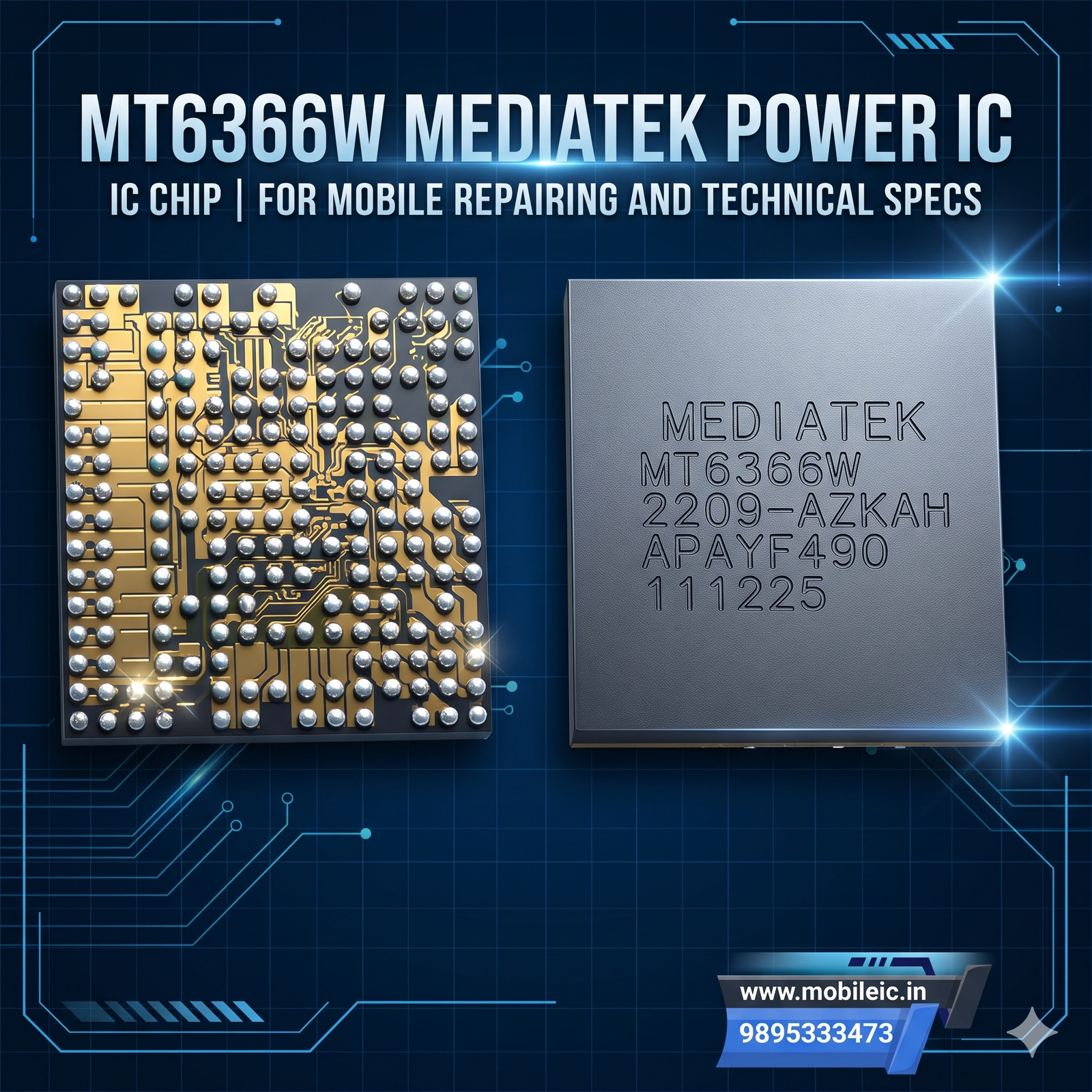
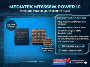
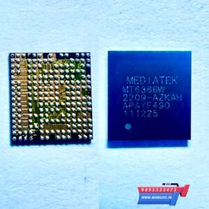
Laser Surface Markings: MEDIATEK MT6366W 2209-AZKAH APAYF490 111225
-
Package Architecture: Fine-pitch Ball Grid Array (BGA)
-
Substrate Layout: Asymmetric solder ball matrix with high-density perimeter signal pins and integrated high-current/ground center layout
-
Pin 1 Reference: Clearly marked dot indicator located on the top left of the package marking
-
Condition: Pre-balled replacement chip ready for direct micro-soldering reflow
Internal Architecture & Operational Functions
The MT6366W integrates multiple internal sub-circuits responsible for overall system initialization and stabilization:
-
Multi-Phase Buck Regulators (DC-DC Converters): Efficiently supplies low-voltage, high-current lines such as CPU Core (VCORE), GPU Core, System Bus, and DRAM Core (VDRAM), minimizing thermal dissipation under heavy system load.
-
Low-Dropout Linear Regulators (LDOs): Delivers clean, low-noise analog voltage rails dedicated to sensitive RF baseband circuits, image signal processors (cameras), touch digitizers, display bias, audio codecs, and environmental sensors.
-
Power Sequence Controller (State Machine): Enforces strict power-up and power-down timing sequences. If any essential rail fails to rise within its designated millisecond window, the controller halts startup to protect the CPU and memory from unaligned bias voltages.
-
System Reset & Sleep Logic: Interfaces directly with the AP via control buses (such as SPM/I2C/SPI control lines) to throttle power output during standby, deep sleep, and active operational states.
-
Thermal & Overcurrent Protection (OCP/OTP): Automatically shuts down primary outputs if onboard shorts trigger excessive current draw or if internal die temperatures exceed safe thermal ceilings.
Hardware Compatibility Reference
(Direct hardware match verified via schematic databases including Borneo Schematics)
Brand |
Handset Model |
Factory Board / Model Code |
Xiaomi / Redmi |
Redmi Note 10 4G |
— |
Xiaomi / Redmi |
Redmi Note 11 Pro 4G |
— |
Xiaomi / Redmi |
Redmi Note 12S |
— |
Xiaomi / Poco |
Poco M4 Pro |
— |
Realme |
Realme 8i |
RMX3151 |
Realme |
Realme Narzo 50 |
RMX3286 |
Infinix |
Infinix Hot 20S |
X6827 |
Infinix |
Infinix Note 11 Pro |
X697 |
Infinix |
Infinix Note 12 VIP |
X672 |
Tecno |
Tecno Camon 18 Premier |
CH9 |
Diagnosing MT6366W Faults (Technician Field Guide)
1. DC Power Supply (DCPS) Current Signatures
-
0 mA Fixed (No Response): Pressing the power key yields zero current change. Usually indicates missing V_{BAT} supply to the PMIC, a damaged internal startup circuit, or a fractured power-key pull-up line.
-
Stuck Current (20 mA – 80 mA): Indicates the PMIC detects trigger input but hangs due to missing secondary voltages (e.g., failed LDO lines) or absence of the reference clock (26\text{ MHz}).
-
Current Jump & Drop (50 mA – 150 mA Rebound): Power sequence initiates but an essential voltage rail collapses under load, prompting an immediate protection shutdown.
-
Instant Short (High Current Draw before Power Trigger): Connecting the board immediately trips the power supply’s current limit. Often points to ruptured internal high-side MOSFETs bridging the primary line to ground.
2. Cold Testing (Diode Mode Readings)
-
Before replacing the chip, test major filter capacitors and buck inductors surrounding the IC using a digital multimeter in diode mode (red probe on ground, black probe on test line).
-
A reading below 0.050\text{ V} or continuous beep on inductors (excluding low-resistance sub-1\text{V} CPU core coils) typically signifies an internal gate puncture within the MT6366W.
3. Thermal Verification
-
Applying voltage with a DC supply while observing the board under a thermal imaging camera or using the rosin atomization method will reveal localized thermal hotspots directly over the MT6366W die surface if internal leakage exists.
Step-by-Step Soldering & Motherboard Installation
-
IC Removal:
-
Shield adjacent plastic connectors and heat-sensitive ICs (CPU, eMMC/UFS) with Kapton tape or thermal barriers.
-
Apply a uniform layer of micro-soldering BGA flux.
-
Set hot-air rework station to 330^\circ\text{C} – 360^\circ\text{C} (adjust based on board thickness and ground plane mass) with moderate airflow.
-
Heat evenly in circular motions until all solder balls melt completely, then lift vertically using anti-magnetic precision tweezers.
-
-
PCB Pad Dressing:
-
Clean the motherboard pad area using lead-free or low-melt solder wire and desoldering braid (wick) to remove residual alloy.
-
Keep the PCB pad flat, level, and free of jagged peaks to prevent solder bridging.
-
Clean thoroughly using electronic-grade isopropyl alcohol (IPA) and inspect under a stereo microscope.
-
-
Placement & Reflow:
-
Apply a microscopic, tacky layer of no-clean BGA flux over the PCB pads.
-
Align the MT6366W precisely to the board’s silkscreen boundary box, matching the Pin 1 dot orientation.
-
Reflow with vertical hot air at 320^\circ\text{C} – 340^\circ\text{C}. Once the alloy liquefies, touch the corner of the chip lightly with tweezers; the chip should self-align and return to its original position via solder surface tension.
-
Allow the board to cool down naturally to room temperature before reconnecting power lines.
-


Leave a Reply